Navigate:
Project Owner: Paul
Started: 2007
I discovered there is nothing difficult about it, you just needed to get the right parts and connect them up.
You need:
- Motherboard with LVDS header in this case its a VIA EPIA M11.
- LVDS module for the mother board. I brought a VIA LVDS-05 Module
- An LCD module that uses the LVDS interface and a compatable back light inverter.
- Cables to connect the LCD to the LVDS module. You will have to make these yourself.
Getting the right LCD is a bit of a gamble. The only thing guranteed at this point is the resolution (provided you have researched correctly) I choose 1024x768. The first was a Sony VAIO which unfortunately had a crack in the LCD - so it was no good. The second was a Compaq Amada M700. I dismantled the screen to find the part number of the LCD Module (which is Toshiba LTM14C421E). Then I was able to locate a data sheet and confirm it used an LVDS interface, get the pin out for it and find the operating voltage (is 3.3V for this one).
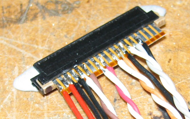
Then I had to make up a cable to connect it to The LVDS module. This involves fiddly fine connectors and wires.
I needed a plug to fit onto the LVDS module and luckily the LCD panel connector from the VAIO laptop fitted perfectly.

The VAIO Connector with a flexible circuit board I found in my junk that had longer contacts than the original allowing me to solder my own wires to it. LVDS signals need twisted pairs made from wires of equal length.

Connect the other end to the LCD module. I decided to connect to the existing wires since they already have the correct plug fitted to the LCD module end.

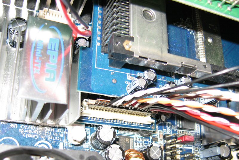
Install LVDS Module on Mother board. Its the board with the VT1631 chip and the white 2 row connector.

Connect up LCD module

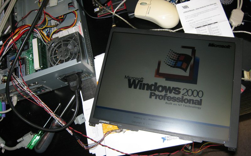
The smoke test proved every thing was done right and compatible.

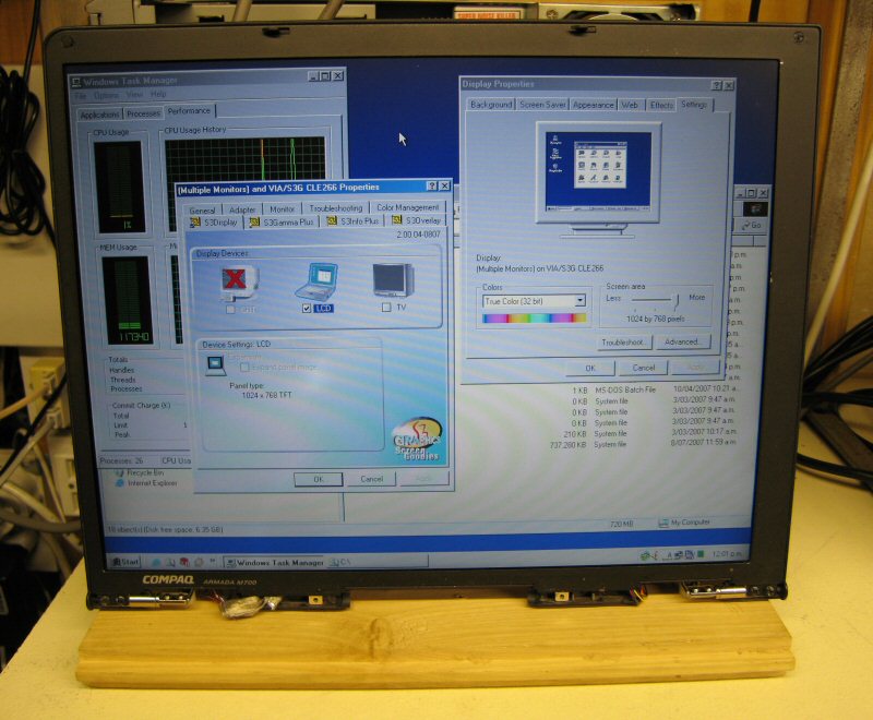
I mounted the LCD to a piece of wood using the laptops original hinges. This works well and it is as functional as a normal brought LCD computer monitor. Its using a digital Interface so there is no need to adjust anything and the picture is always sharp and clear.
I was not able to find any pin out details or specification for the back light inverter. Using common sense and some bench power supplies I was able to identify the Power, ON/OFF, and brightness lines and that it runs from 12V, so it is run stright off a disk drive power conector. I used trimpots to divide the 12V down to the required voltages for the ON/OFF and brightness lines.
The back light ON/OFF line could be connected to the LVDS module which would allow windows to control it.